요약
“t”는 영문자로, 한글로는 표현이 불가능합니다. 다른 내용으로 질문해주시면 도움드리겠습니다.
도표 설명

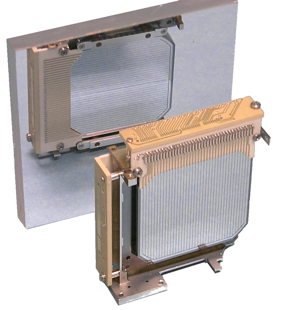
The image shows two computer hardware components, which appear to be part of a microcomputer or other electronics system. On the left is a metal heatsink, typically used in electronic devices to dissipate heat generated by the device’s internal components. It has a large surface area and multiple fins that facilitate airflow to cool down the heatsink during operation.
On the right is a copper-colored circuit board with various electronic components attached to it. The board has a mix of integrated circuits (ICs), resistors, and possibly some connectors or other hardware. This type of circuit board is common in many types of computers and microcontrollers.
Both items are clean and seem to be new, as indicated by the absence of dust or signs of wear. They are photographed against a neutral background which emphasizes their design and function.

The image depicts a schematic of an experiment or scientific setup, likely related to physics or engineering. It includes several labeled components, which are typical for circuits or electronic systems:
1. A battery source (Vcc) with a voltage value of 5V, which provides power to the circuit.
2. An electrode, labeled “Electron-collecting electrode,” which is typically used in electrochemistry to collect electrons as they move between two electrodes during an electrochemical reaction.
3. A test tube containing a solution, possibly related to the experiment.
4. A pH indicator, which likely measures the acidity or basicity of the solution.
5. An electric circuit with a charge-trapping hole and a voltage dropper, suggesting that this setup is measuring the electron flow or charge accumulation in the system.
6. A phosphor tube with a phosphorescent screen, which is a type of vacuum tube used for its ability to emit light without heating up.
7. An optical sensor with a photodiode and an associated amplifier, indicating that the experiment may involve measuring or detecting light.
8. A probe that is presumably collecting data related to the experiment, such as voltage, current, or charge flow.
9. A free electron hole, which could be part of a vacuum tube system.
10. Other circuit elements, such as resistors and capacitors, which are part of the overall electronic configuration.
The diagram is accompanied by a text that reads: “HV; 5V, electro-collection electrons, pH meter, charge-trapping hole with V dropper, phosphorescent screen, photodiode amplifier.” This suggests that the experiment involves high voltage (HV) settings, and it is designed to collect and measure electrons using a pH meter, a charge-trapping hole with a voltage dropper, and a photodiode amplifier. The setup seems to be related to electrochemical reactions or measurements in a vacuum environment.

This image appears to be a graphical representation of an electrophysiological experiment or concept, possibly related to neural communication or signal processing in the brain. Here’s a description of what the image is showing:
1. **Collection Signal (Red Arrow):** The red arrow labeled “Electron collection signal” represents an electrical signal that seems to be collected over time, which could be from neurons or any other electrical activity within the brain.
2. **Time-lapse Graph (Blue Line):** The blue line graphically shows how the signal changes over time. There are two labels on the x-axis: “V” and “E,” which likely refer to voltage (potential difference) and energy levels, respectively. There’s also a unit of measurement for the y-axis labeled “V,” suggesting that the vertical axis represents voltage as well.
3. **Signal Amplitude (Blue Line):** The amplitude of the signal is indicated by the peak height of the blue line at different time points. As time progresses, the amplitude of the signal increases and then decreases.
4. **Charge Calculation (Green Arrow):** A green arrow labeled “Q” indicates a charge calculation, which might be related to an electrostatic potential or another form of electrical potential energy. The calculation is shown as “Q = E • 2.89eV,” where “E” is the voltage across the membrane and “2.89eV” could be the energy change per unit charge.
5. **Difference (Δ) on the Y-axis:** There’s a vertical dashed line labeled “Δ,” which might represent an incremental or differential quantity in the context of the signal or charge calculation.
6. **Hole Collection Signal (Blue Arrow):** Another blue arrow labeled “Vh” represents another collection signal, possibly associated with holes in a membrane or a different form of signal transmission. The difference between this signal and the main signal (collection signal) is indicated by the double-ended vertical arrows pointing to the “V” label on the y-axis.
7. **Synaptic Signal (Black Arrow):** A black arrow labeled “ΔVs” could be representing a change in voltage over time at a synapse, which is the junction between two neurons where chemical signals are transmitted.
Overall, this image seems to illustrate the complex dynamics of electrical activity within a neural system, including the collection and transmission of different types of electrical signals across membranes or between cells. It’s important to note that without additional context, it is not possible to provide a detailed scientific explanation for each element in the image.
